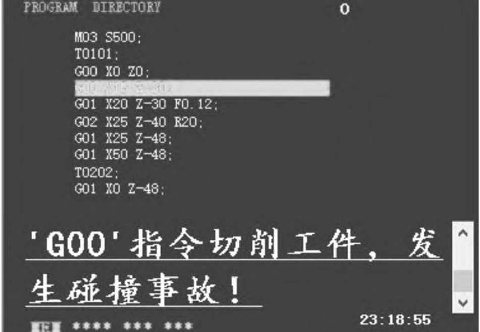
개요 : 실습 및 학습을 목표로하는 NC 선반 시뮬레이션 시스템은 VB 6에서 설계되었습니다. 0이다. N091 NC 선반이 장착 된 Fanuc-Oi Mate TB NC 운영 시스템을 시뮬레이트하는이 시스템은 NC 코드 작성, 코드 오류 검사, 부적절한 공정 특성에 대한 경고, PC에서의 공정 및 작동 교육 시뮬레이션과 같은 기능을 실현합니다. 강사는이 NC 시뮬레이션 시스템을 통해 N091 NC 선반을 조작하는 기술을 쉽게 익힐 수 있습니다.이 NC 시뮬레이션 시스템은 유기적으로 시각적으로 학습과 교습을 결합합니다. 이 논문에서는 설계, 핵심 기술 및 프로그램 코드를 소개합니다. 핵심 단어 : N091 NC 선반; VB 6. 0 소프트웨어; NC simulation0 서문 과학 기술의 진보와 함께 현대 제조를위한 기본 장비 인 CNC 공작 기계는 기계 제조 자동화, 유연성 및 통합이되었습니다. 변환의 중요한 기초와 핵심 내용. 최근 몇 년 동안 국내 대학은 학생들의 엔지니어링 실무 및 공학 인식을 교육하기 위해 수치 제어 공작 기계를 기반으로 엔지니어링 교육을 수행하는 엔지니어링 교육 센터를 설립했습니다. 현재 CNC 교육에 필요한 이론적 설명 이외에도 공작 기계의 경우 대부분의 작업은 해당 기능을 갖춘 실제 시스템 (실제 NC 공작 기계 또는 교육 시스템)에서 수행해야합니다. 수치 제어 제품은 고가이며 공장의 CNC 공작 기계는 비교적 무겁습니다. 처리 작업은 트레이너의 오용을 고려하여 공작 기계 장비 및 심지어 운전자 자신의 개인 안전을 위태롭게 할 수 있습니다. 따라서 대형 CNC 교육은 학생들이 실제 공작 기계에서 CNC 공작 기계 공학 교육을 사용하는 데 적합하지 않습니다. 가상 장비는 CNC 공작 기계의 기능 및 상태 시뮬레이션을 수행하는 교습 캐리어로 사용됩니다. 학생들은 데스크톱 또는 노트북을 사용하여 CNC 공작 기계의 프로그래밍 및 수동 작동 방법에 익숙해 질 수 있습니다. 수치 제어 장비의 느린 업데이트 문제는 소프트웨어에 대화식 강의 기능 모듈을 통합하여 해결할 수도 있습니다. 특정 구현 프로세스는 장비, 사이트 및 시간에 제한받지 않고 경제적이며 안전하며 적시에 업데이트 된 교육 리소스를 확보 할 수 있습니다. 걱정없이, 그것은 경제적으로 기술적으로 가능하며 명백한 교시 효과가있는 솔루션입니다. 현재 중국의 NC 교육 분야에서 탁월한 시뮬레이션 소프트웨어는 주로 Nanjing Siwo, Shanghai Yulong 및 Beijing Feike의 세 가지 소프트웨어를 포함합니다. 이 세 가지 유형의 소프트웨어는 시뮬레이션 NC 시스템, 공작 기계 및 기능의 수에 따라 길이와 유형이 다르지만 시뮬레이션 목표는 거의 같습니다. 이들은 기능 및 프로토 타입 시스템, 즉 데이터 처리의 관점에서 가상 장치의 일관성을 추구합니다. 시뮬레이션 객체의 일관성은 주로 시뮬레이션 프로토 타입 CNC 시스템의 디코딩 및 보간 프로세스와 일치합니다. 정확히 말하자면, 위에서 언급 한 소프트웨어는 프로토 타입 장치에 의해 적절하게 처리되지 않을 수있는 프로그래밍 오류를 인식하지 못한다는 기능적 원리의 견지에서 프로토 타입 장치와의 유사성을 추구하기 때문입니다. 장치 고장. 기존 시뮬레이션 소프트웨어의 초점은 공작 기계 몸체가 데이터 정보에 따라 올바르게 움직일 수 있는지 여부이므로 작동 세부 사항 및 작동 습관에 대해 운영자가 조작 사고를 일으킬 수 있다는 우려는 없습니다. 이것은 장비 고장의 주된 이유입니다.이 프로젝트는 N091 CNC 선반을 프로토 타입 객체로 사용하고 VB 6.0 언어의 강력한 인터페이스 설계 기능을 사용하여 CNC 선반의 작동 모드 및 작업 프로세스를 효과적으로 시뮬레이트하는 방법을 효과적으로 개발합니다 CNC 선반 가공 프로그램의 정확성을 테스트하고 실시간으로 애니메이션을 표시하십시오. 시뮬레이션 소프트웨어. 장비의 기능을 시뮬레이션하는 것 외에도, 소프트웨어는 CNC 선반 엔지니어링 교육의 안전성에있어 학생들이보다 쉽게 만들 수있는 네 가지 유형의 오류에 중점을 둡니다. 학생들이 효과적인 프로그래밍 스타일과 작동 습관을 효과적으로 이끌도록하기 위해 소프트웨어는 NC 프로그램 처리 과정을 적절하게 설계하도록 설계되었습니다. 보고서의 세부 사항은 보안 사고를 유발하는 다양한 문법적 오류를 즉시보고하고 절삭 매개 변수와 같은 프로세스 데이터를 자동으로 조정할 수 있습니다 .1 시스템 전체 설계이 시스템은 N091 CNC 선반이 장착 된 Fanuc-0i Mate TB 수치 제어 시스템을 사용합니다 주요 시뮬레이션 개체로. 부품 공 공 및 가공 공구를 완벽하고 명확하게 표시하고 NC 가공 프로세스를 상세하게 시뮬레이션 할 수 있으며 작동 방법이 간단합니다. 훈련 된 학생들은이 소프트웨어를 사용하여 CNC 공작 기계없이 CNC 공작 기계 작동 방법을 연습하고 일반적인 기본 명령으로 구성된 CNC 가공 프로그램을 디버그하고 동적 부품 실시간 처리 프로세스를 표시하고 가공 결과를 관찰 및 분석하며 시간에 부품 가공 프로그램을 발견하십시오. 오류 및 가능한 간섭. 시스템의 모듈은 높은 결합력과 낮은 커플 링의 원칙에 따라 설계되었습니다 .2 시스템 핵심 기술 구현 가상 NC 가공 프로세스에서 가상 기계 도구는 NC 코드를 직접 실행할 수 없습니다. 따라서 번역 모듈은 먼저 NC 코드를 가상 컴퓨터가 인식하고 실행할 수있는 aA 코드로 변환해야합니다. 이 시뮬레이션 수치 제어 시스템 개발의 어려움은 수치 제어 코드의 읽기, 디코딩, 오류보고 및 자동 조정 측면에 있습니다. 기계 기능의 실제 시뮬레이션 외에도 시뮬레이션 NC 시스템 개발의 초점은 학생들에게 기계 작동 방법을 익히고 올바른 작동 습관을 개발하도록 유도하는 것입니다. 1 NC 코드 전처리 NC 코드의 전처리에는 소스 메모리 주소에서 프로그램 파일을 읽는 작업, 주석문, 빈 문장 및 빈 줄과 같은 NC 코드의 불필요한 기호를 삭제하고 소문자를 대문자로 변환하는 작업 및 각 문자 앞에 공백을 추가하십시오. 읽은 NC 코드를 읽기 쉽게 만드십시오.이 시스템을 설치하면 TXT 형식의 NC 코드 파일을 만들 때 컴퓨터의 지정된 폴더에 저장해야한다는 것을 상기시켜줍니다. 이런 식으로 작업자가 조작 패널의 PROG 버튼을 클릭하면 VB 프로그램에서 File1이라는 FileListBox 컨트롤의 Path 속성이이 폴더에 저장된 모든 NC 프로그램 파일 이름을 지정된 폴더. RichTextBox3에서 운전자는 기계 디스플레이 패널의 프로그램 선택 창에서 파일 이름을 기준으로 NC 프로그램을 선택할 수 있습니다. 외부 파일에서 순차적으로 명령문을 읽는 Line Input 문은 VB에 통합되어 있으며 읽기 내용이 문자열. N091 CNC 선반의 FANUC-0i MATE TB 시스템에서 NC 프로그램은 현재 코드 입력 줄을 세미콜론으로 종료하고 커서를 아래로 이동하여 다음 코드 입력 줄을 시작합니다. VB는 줄 바꿈 플래그로 vbCrLf 또는 Chr (13) 및 Chr (10)을 사용하므로 외부 적으로 파일을 읽는 것이 줄 바꿈을 줄 바꿈으로 시스템에 읽힐 수 있으며 줄은 표시 패널의 "세미콜론 + 줄 바꾸기"로 구분됩니다 (RichText-Box1). 관련 코드는 다음과 같습니다 : TextLine = Split (RichTextBox1. Text, vbCrLf) 'RichTextBox1. Text = ""행의 경우 0 UBound (TextLine) RichTextBox1. SelColor = vbYellowRichTextBox1. SelText = RichTextBox1. SelText & TextLine (행) & Chr (13) & Chr (10) RichTextBox1. SelColor = vbYellowNext rowSemicolon TextLineInternally에서 VB는 Replace 함수와 Trim 함수를 통합합니다. 바꾸기 기능은 NC 코드가 소문자에서 대문자로 변경되도록 ASC 코드로 변환 할 수 있습니다. 자르기 기능은 코드 줄의 시작과 끝 부분에서 공백을 삭제할 수 있습니다. 빈 줄을 제거하려면 Len 함수를 사용하여 0인지 확인하십시오. 값이 0이면 빈 줄을 의미하고 NC 코드 Textline ()의 String을 저장합니다. 행 번호 변수 MoveRow에 의해, 다음 행은 공백 행인 Textline (MoveRow + 1)에서 Textline (MoveRow)입니다. ; 둘 이상의 빈 줄이 있으면 루핑 코드로 제거 할 수 있습니다. 코드 구현은 여기에 설명되어 있지 않습니다 .2. 2 NC 코드 검사, 공정 데이터 오류 기능 NC 코드 검사의 경우 NC 코드 구문 규칙 외에도 처리 일정이 합리적인지 여부를 고려하는 것이 더 중요합니다. 이 기사에서는 다음 세 가지 예제를 사용하여 솔루션을 분석하고 관련 코드를 보여줍니다. 2. 1 G00 명령은 공작물 절단을 금지합니다. CNC 선삭 작업의 경우 G00은 빠른 점 포지셔닝 명령입니다. 이 명령에서, 공구는 CNC 시스템의 미리 설정된 기계 파라미터 값에 따라 좌표축을 따라 빠르게 이동합니다. 실제 가공에서 부주의 또는 부주의로 인해 절삭 공정 중에 G00 명령을 사용하면 공작 기계는 오류를보고하지 않고 직접 명령을 실행합니다. 이것은 필연적으로 충돌 사고로 이어지고 공작물과 공구를 파괴합니다. 시뮬레이션 시스템은이 문제를 NC 프로그램에서의 의미 론적 분석의 부재로 돌렸다. 시뮬레이션 가공 중에 공구가 G00 명령에 따라 공작물 원주 표면으로 이동하면 시스템이 알람 정보를 제공합니다. 인터페이스는 그림 1에 나와 있습니다. 그림 1 알람 정보 인터페이스이 정보는 프로그램에서 커팅 명령이 잘못 적용되었음을 프로그래머에게 알립니다. 실제 가공에서 공구와 공작물 간의 충돌이 발생합니다. 이 기능을 시뮬레이션 시스템에 추가함으로써 초보자 학생들의 프로그래밍 습관을 크게 향상시켜 실제 프로그래밍에서 오류를 일상적으로 피할 수 있습니다. 이 기능을 달성하기 위해 시스템은 NowData () 배정 밀도 그룹을 정의하여 즉시 공구 위치 좌표를 저장합니다. 이 중 NowData (1)는 현재 선삭 공구 z의 좌표 값을 저장하고 NowData (2)는 현재 선삭 공구의 좌표 값 x를 저장합니다. 시스템은 제한된 디스플레이 인터페이스에서 블랭크의 길이를 표시 할 수 있는지 여부를 고려하기 때문에 블랭크 크기 매개 변수를 여기에 bl로 설정하십시오. 이 때 NowData ()의 좌표 값에 시뮬레이션 인터페이스의 매개 변수 bl가 곱해집니다. 여기서 공작물 좌표계의 원점은 공작물의 오른쪽 끝 단면과 축의 교차점에 설정되고 프로그램의 원점이 결정됩니다. 따라서 G00 명령 아래에서 현재 공구가 절삭 동작 중인지 여부를 판별하려면 두 가지 조건 만 결정하면됩니다. 1) 공구 좌표 z가 음수인지 여부. 2) 공구의 좌표 값 x가 공작물 블랭크의 반경보다 작은 지 여부, 즉 NowData (1)가 0보다 작은 지, NowData (2)가 공작물 반경보다 작은 지 확인합니다. NowData (2)의 값 x가 실제 값에 bl를 곱한 값이므로 입력 공백 직경의 값에 부등호 기호의 오른쪽에 bl가 곱해 지므로 부등식 결정이 유효하며 수학 표현식으로 표현됩니다 즉 z <0이고 x <workpiece. Blank diameter × bl /2. If the system determines that a collision occurs during operation, an alarm will be given and the program will be reprogrammed. The following is the code to implement this feature:If g00 = True ThenIf NowData( 1) < 0 And NowData( 2) < Form2. Text1. Text*bl / 2 Thenmianban. RichTextBox2. SelColor = vbRedmianban. RichTextBox2. SelText = mianban. RichTextBox2.SelText &” ‘G00’命令下禁止切削工件,请重新编写程序,再次运行! “PlaySound ” warn. wav”mianban. temg. Text = ” - - ALM - - ” : mianban. temg.Visible = TrueTimer5. Enabled = TrueTimer16. Enabled = FalseAlm( 116) = True2. 2. 2 cutting parameter out of range alarmThe reasonable setting of cutting parameters directly affects the machining quality of parts. In actual production and processing, due to carelessness or unfamiliarity with the cutting parameters, the setting of the feed amount per revolution of the turning tool may cause problems. The amount of tool feed depends on the surface roughness and the cutting force. When rough-cutting, the surface roughness is not high, and the feed is mainly caused by the knife.The precision and strength of rods, blades, workpieces and machine tools are determined by the cutting forces. When semi-finishing and fine-cutting, the economics of cutting are mainly considered. That is to say, the cutting load cannot exceed the power of the machine tool while ensuring the economic life of the tool. Therefore, the tool feed amount cannot be too large or too small. If an oversight or error occurs during programming, an error will be indicated in the code detection of the simulation system. The simulation system provides that the spindle feedrate of one revolution must not be less than 0. 05mm or greater than 0. 5mm (The amount of cutting is closely related to the workpiece material and the tool type and material. The value range of this feed amount is in most cases. For other individual cases, it can be determined by referring to the manual or cutting test).A line of NC code is read in the FileDebugger of the system code. If the feed “F” is found from this line of code by the Mid function, then the custom GetNumber function is used to convert the number immediately followed by F to a single-precision floating-point number. 0. 05 and 0. 5 if less than 0. 05mm or greater than 0. 5mm, then the alarm prompts, its interface is shown in Figure 2.Fig. 2 Feed range out of range alarm prompt interface2. 2. 3 tool instruction alarm errorIn CNC turning, the tool command T is used to select the tool and its corresponding tool compensation. Example: T0202 represents the No. 2 knife and the No. 2 knife make-up. Therefore, it is agreed in this paper that the tool number and its tool complement number are the same value, which is not easy to confuse. If the tool number and the tool compensation number do not match in the NC program or one of them is default, the coordinate system will be disordered and the machining code will not be executed correctly. The system stores 3 commonly used tools: T0101 for 93° roughing tool; T0202 for cutting tool; T0303 for fine turning tool. If “T” appears in a row and the following number is not the above number, the system will indicate which row of tool number T is illegal. code show as below:If TExist = True Then Call ErrCase( 3,FileRow,CaseType)TExist = TrueNumberString = GetNumber ( Right ( TextLine,Len ( TextLine ) -NumberStart) )If NumberString = ” ” ThenCall ErrCase( 1,FileRow,CaseType)ElseNumberStart = NumberStart + Len( NumberString)CaseNumber = CDbl( NumberString)If CaseNumber = 101 Or CaseNumber = 202 Or CaseNumber = 303Or CaseNumber = 404 Then ‘刀具编号ElseCall ErrCase( 9,FileRow,CaseType) ‘ 此处调用 ErrCase 函数显示错误信息End IfEnd If3 system learning functionThis simulation system is used as a teaching aid for engineering training. Students can use this software to conduct self-study, develop good programming styles and operating habits as starting points, and conduct detailed studies on module settings, selection of interaction methods, and logic arrangement of actions.3. 1 Simulation System InterfaceIn order to enable the trainees to quickly get acquainted with the actual machine tool, the software simulates the real machine tool as much as possible in the interface design. The simulation system interface is shown in Figure3.3. 2 Operation Panel Button Function TipsFor trainees who have not touched the N091 CNC lathe or the software, there are dozens of knobs and buttons on the control panel. The system uses the ToolTipText property in the Command control that comes with the VB platform, and the corresponding knob or The name of the button is filled in the operation panel. When the mouse is moved to the corresponding position, the system will give a text prompt. The interactive function is good, which is very helpful for students self-study. The function prompt interface of the machine tool operation panel is shown in Figure 4.Figure 3 Simulation System InterfaceFig. 4 Tool operation panel button function prompt interface3. 3 lathe operation sequence trainingAfter investigating the commercialized CNC simulation software on the market, the author found that most of the software does not strictly regulate the operation sequence of the machine tool. If the trainee has not touched the CNC lathe, the complex operation interface will be at a loss and I do not know where to go. If you start, you will soon lose interest in learning. In view of this, the simulation system uses VB to solve the above problem with the visible property of the Command control, and the order is limited by the selection of the property false/true visible to this control in the Command_Click( ) function. If the operation sequence is wrong, it triggers. MsgBox, prompt error information, operation sequence warning interface as shown in Figure 5.Figure 5 Operation Sequence Warning InterfaceFigure 6 Interpolation Principle Learning Module Interface3. 4 interpolation principle learning moduleLinear interpolation and arc interpolation are the most basic tool path generation methods for CNC lathes. The above two types of interpolation in the N091 CNC lathe are implemented using a point-by-point comparison method. The simulation system embeds an interpolation learning module, and students can select the circumcircle, inverse circle, and linear interpolation in the interpolation learning window, and give the starting and ending coordinates accordingly to generate a circle or a straight line. Realize the consolidation of classroom knowledge teaching. The interpolation principle learning module interface is shown in Figure 6.4 ConclusionThis software is aimed at the training and teaching of CNC lathe engineering. It aims at cultivating engineering practices and focuses on the development of self-learning functions. Students participating in the CNC lathe engineering training can use the computer at any time to carry out simulations of CNC lathe machining procedures, lathe operation methods, and learning of related CNC knowledge. While significantly improving the training effect, it effectively ensures the safety of equipment and trainees. It actually solves the problem of excessive man-machine ratio caused by a large number of students and limited training equipment in the school’s CNC lathe engineering training, and improves the operation practice. The efficiency reaches the goal of the students to better learn the CNC machining process.
출처 : Meeyou Carbide